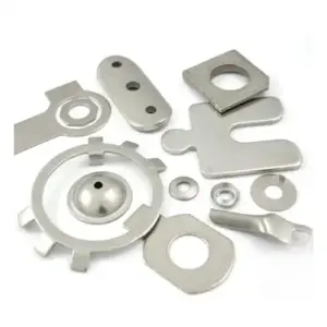
Designing sheet metal parts for manufacturing requires more than achieving the required geometry. Hole spacing, bend radii, feature location, flange dimensions, and tooling access can all affect dimensional accuracy, tooling life, production stability, and overall manufacturing cost.
By considering manufacturability during the design stage, engineers can reduce tooling problems, minimize production interruptions, and improve consistency in high-volume production.
Below are several practical DFM considerations for precision metal stamping and forming.
1. Maintain Adequate Spacing Between Adjacent Holes
The minimum ligament between adjacent holes should be sufficient to maintain material strength and prevent excessive stress concentration in the tooling.
As a general guideline, the distance between adjacent features should be evaluated relative to the material thickness, hole diameter, material strength, and tooling configuration.
For many applications, a minimum ligament of approximately 1.5 × material thickness can be used as an initial design reference. However, the actual minimum should be validated based on the material and tooling design.
When features must be placed closer together, the tooling strategy may need to be modified. This can include changing the punching sequence, using staggered punching operations, or introducing additional forming or machining operations.
Hole Geometry and Tooling Considerations
Different hole geometries have different effects on punch strength and tool life.
Round holes are generally the most robust and easiest to manufacture and maintain because they distribute stress relatively evenly around the punch.
Square holes can provide a high opening ratio and efficient use of space, but their sharp corners create higher stress concentrations and may increase the risk of punch wear or fracture.
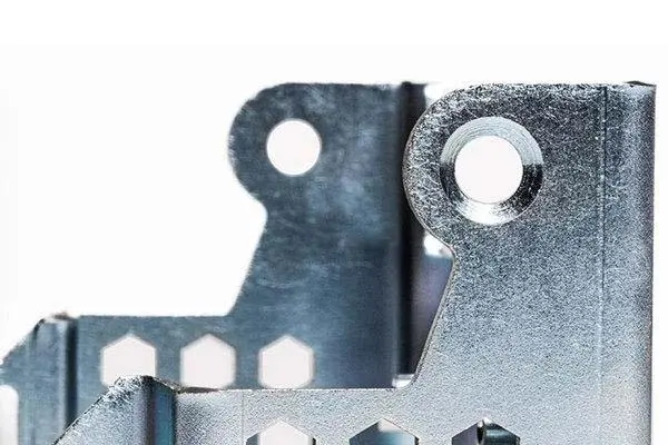
Hexagonal or other polygonal holes can provide an alternative where geometry or space utilization is important, although their tooling requirements should be evaluated according to the application.
For high-volume production, hole geometry should therefore be considered together with tooling life, maintenance requirements, and production volume.
2. Consider Burr Direction During Part and Tool Design
Blanking and punching naturally produce a sheared edge with a burr.
The burr height generally increases as the punch and die clearance changes or as the tooling becomes worn during production.
For components that will be handled, assembled, or exposed to electrical wiring, burr direction and edge condition can be important functional and safety considerations.
During tooling and drawing development, the required burr direction should be clearly defined where it affects:
- Assembly
- Operator safety
- Electrical insulation
- Sealing
- Appearance
- Contact surfaces
Where necessary, secondary deburring or edge-finishing operations can be specified.
3. Understand the Punching Shear Profile
A punched hole does not have a perfectly vertical shear surface throughout the material thickness.
A typical punched edge consists of several characteristic regions, including:
- Roll-over
- Burnished or smooth shear zone
- Fracture zone
- Burr
The exact proportions depend on material type, thickness, tooling clearance, punch geometry, and machine conditions.
For precision tooling, the punch and die dimensions should be established according to the required finished feature and the applicable tooling clearance.
For example, when determining the size of a punched hole, the relationship between the required hole dimension and the punch diameter must be considered. For blanked external profiles, the die opening and punch dimensions must similarly be designed according to the required finished part dimensions and material clearance.
This relationship should be established during tooling design rather than treated as a universal fixed rule.
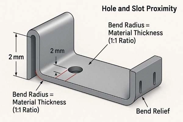
4. Provide Bend Reliefs Near Bends
When a sheet metal feature extends across or close to a bend, material deformation can cause tearing, bulging, or distortion at the bend transition.
A bend relief can be introduced at the end of the bend line to control material flow and prevent unwanted deformation.
A rounded relief or slot is often used depending on the part geometry.
As an initial design reference, the relief width and length should be related to material thickness and bend geometry. However, the appropriate dimensions depend on the material, bend radius, bend angle, and forming process.
Bend reliefs are particularly important when holes, slots, or cutouts are located close to a bend.
5. Specify an Appropriate Inside Bend Radius
The inside bend radius should be selected according to the material type, material thickness, bend process, and tooling.
For many sheet metal applications, an inside bend radius of approximately 0.5 × material thickness or greater may serve as an initial reference for ductile materials.
However, this should not be treated as a universal rule.
High-strength steel, stainless steel, aluminum alloys, and other materials may require different bend radii to prevent cracking or excessive springback.
If a drawing does not specify a bend radius, the required radius should be established according to the material and manufacturing process.
A properly selected bend radius can improve:
- Forming stability
- Tool life
- Dimensional consistency
- Resistance to cracking
- Overall production reliability
6. Use Reinforcing Features to Improve Structural Rigidity
Long, narrow sheet metal components are more susceptible to deformation, vibration, and loss of straightness.
Where a continuous flange or return cannot be incorporated into the design, reinforcing features can be added to increase stiffness.
Possible solutions include:
- Embossed ribs
- Gussets
- Local flanges
- Formed stiffeners
- Beads or beads-in-panel structures
These features increase the section stiffness without requiring a significant increase in material thickness.
Their geometry should be designed to avoid interference with adjacent components and to remain compatible with the available forming tools.
7. Avoid Narrow Openings Too Close to Bend Lines
Slots and openings located too close to a bend can deform during forming.
When an opening is close to the bend transition, material flow during bending may distort the opening, create tearing, or produce an undesirable edge condition.
Where possible, openings should be positioned sufficiently far from the bend line.
If the design requires an opening close to a bend, a bend relief can be incorporated to isolate the opening from the bending deformation.
The required relief dimensions depend on material thickness, bend radius, bend angle, and feature geometry.
8. Avoid Sharp Internal and External Corners
Unless a sharp corner is functionally required, sheet metal features should generally incorporate an appropriate radius.
Sharp corners can create stress concentrations during forming and can also create difficult tooling conditions.
For stamped components, sharp internal corners in the die can increase the risk of cracking or chipping. Sharp punch tips can also be vulnerable to wear or fracture.
Adding an appropriate radius can:
- Improve tooling strength
- Reduce stress concentration
- Improve material flow
- Increase tool life
- Reduce burr formation
- Improve production stability
Corner radii should therefore be considered during both part design and tooling development.
9. Design Flanges With Sufficient Height
Flanges are widely used to increase structural rigidity, provide fastening surfaces, and create interfaces between sheet metal components.
For thin-gauge sheet metal, a flange height of approximately 3 × material thickness or greater may be used as an initial reference in some applications.
However, the actual minimum flange height depends on:
- Material thickness
- Bend radius
- Tooling configuration
- Bend angle
- Part geometry
- Required dimensional tolerance
When higher dimensional accuracy is required, the bend sequence and tooling configuration should be considered during the DFM stage.
10. Keep Features Away From Bend Transitions
Holes, slots, embossments, and other formed features should not be positioned too close to a bend unless the design specifically accounts for the resulting deformation.
Features located close to a bend may experience:
- Distortion
- Elongation
- Dimensional shift
- Local deformation
- Surface damage
When the feature must remain close to the bend, a bend relief or other design modification may be required.
The minimum feature-to-bend distance should be established according to material thickness, bend radius, feature size, and the forming process.
11. Use Bend Reliefs to Protect Openings
When an opening extends close to a bend, a properly designed relief slot can isolate the opening from the bending deformation.
The relief should be long enough to accommodate material movement and wide enough to prevent unwanted tearing or deformation.
This is especially important for:
- Cable openings
- Ventilation slots
- Mounting holes
- Connector cutouts
- Large access openings
A well-designed bend relief can significantly improve dimensional consistency and reduce secondary rework.
Good sheet metal design begins with manufacturability.
Hole spacing, bend reliefs, inside radii, flange dimensions, feature-to-bend distances, and reinforcing structures all have a direct impact on tooling performance, part quality, production efficiency, and manufacturing cost.
precision metal stamping prats used in AI server infrastructure, energy storage systems, liquid cooling equipment, telecommunications equipment, and industrial applications, these considerations become particularly important when tight tolerances and high-volume production are required.
In the Techsun, DFM analysis is integrated into tooling and process development to evaluate material behavior, forming feasibility, tooling access, dimensional requirements, and production efficiency before mass production begins.