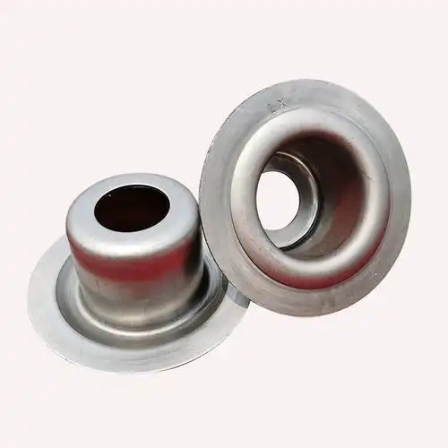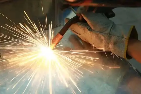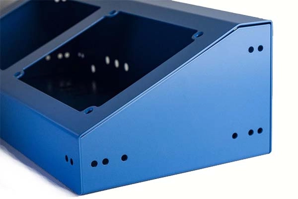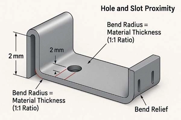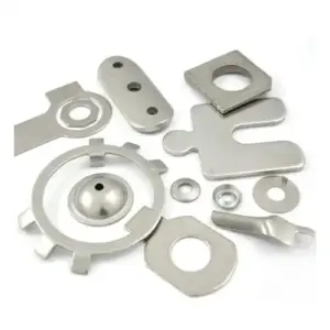
Manufacturing server rack enclosures and other precision sheet metal components requires careful control of material properties, tooling accuracy, forming parameters, and dimensional tolerances.
During deep drawing and other forming operations, defects such as dimensional variation, wrinkling, cracking, surface damage, and shape distortion may occur if tooling or process parameters are not properly controlled.
Understanding the root causes of these defects allows manufacturers to implement effective corrective actions and improve production stability.
Dimensional Inconsistencies
1. Insufficient Height of Deep-Drawn Parts
Possible Causes
-
The blank size is too small.
-
The punch-to-die clearance is insufficient.
-
The punch corner radius is too small.
Corrective Actions
-
Increase the blank size within the allowable process range.
-
Adjust the punch-to-die clearance or replace the punch or die if necessary.
-
Increase the punch corner radius according to the forming requirements.
2. Excessive Height of Deep-Drawn Parts
Possible Causes
-
The blank size is too large.
-
The punch-to-die clearance is excessive or otherwise outside the specified range.
-
The punch corner radius is too large.
Corrective Actions
-
Reduce the blank size as required by the process specification.
-
Adjust the punch-to-die clearance through precision machining or component replacement.
-
Reduce the punch corner radius according to the specified tooling geometry.
3. Uneven Wall Thickness or Part Tilting

Possible Causes
-
Misalignment between the punch and die causes uneven clearance.
-
The die is misaligned with the positioning components.
-
The punch axis is not perpendicular to the die surface.
-
Blank holder force is uneven.
-
The die geometry is inconsistent or has been worn or damaged.
Corrective Actions
-
Correct the alignment of the punch and die to ensure concentricity.
-
Adjust and accurately position the locating components.
-
Correct the punch or die alignment.
-
Adjust and balance the blank holder force.
-
Rework or replace the affected die component as required.
Wrinkling
Wrinkling is a common forming defect, particularly in deep-drawing operations. It generally occurs when the sheet material is not sufficiently restrained during forming.
Possible Causes
-
Blank holder force is insufficient or uneven.
-
Punch-to-die clearance is excessive or improperly controlled.
-
Material thickness is below specification, or the material has insufficient formability.
-
The die corner radius is too large.
-
The actual blank holder conditions do not match the process requirements.
Corrective Actions
-
Adjust the blank holder force to achieve stable material flow.
-
Optimize the punch-to-die clearance or replace the affected tooling components.
-
Verify the material grade, thickness, and mechanical properties and replace the material if necessary.
-
Optimize the die corner radius or modify the blank holder configuration.
-
Verify the blank holder setup and ensure that it matches the approved process parameters.
Cracking and Fracture
Cracking or fracture typically occurs when the material is subjected to excessive tensile stress during forming. It can be caused by material properties, tooling geometry, excessive restraint, insufficient clearance, or an unsuitable forming process.
Possible Causes
-
Material quality is inadequate, including surface defects, scratches, excessive roughness, or inconsistent material properties.
-
Blank holder force is excessive or uneven, restricting material flow and causing excessive thinning.
-
The die corner radius is rough, damaged, worn, or cracked.
-
The die corner radius is too small, resulting in excessive material thinning.
-
Punch-to-die clearance is too small, increasing forming stress and material thinning.
-
Process parameters such as lubrication, annealing, or intermediate forming operations are inappropriate.
-
The punch corner radius is too small.
-
The blank edge has excessive burrs or does not meet the specified edge-quality requirements.
-
The blank size or geometry is incorrect.
-
The punch and die are not properly aligned or parallel.
-
The drawing ratio is too aggressive for the material and forming operation.
Corrective Actions
-
Verify the material specification and replace the material if necessary.
-
Inspect, repair, or replace damaged tooling components.
-
Adjust the blank holder force to improve material flow.
-
Increase the die corner radius where appropriate.
-
Optimize the punch-to-die clearance through precision machining.
-
Review and optimize lubrication, heat treatment, annealing, and other process parameters.
-
Increase the punch corner radius where appropriate.
-
Improve the blanking process and remove excessive burrs.
-
Optimize the blank size and geometry.
-
Correct punch and die alignment.
-
Add intermediate forming operations or redistribute the deformation across multiple stages.
Surface Damage, Scoring, and Galling
Surface defects can occur when the material slides against the tooling under high forming pressure. In aluminum and stainless steel forming, galling and material transfer can be particularly important concerns.
Possible Causes
-
Punch-to-die clearance is insufficient or inconsistent.
-
Die corner surfaces are rough or improperly finished.
-
The die working surfaces or material surfaces are contaminated.
-
Tool hardness or surface treatment is inadequate, allowing material to adhere to the tooling.
-
Lubrication is insufficient or the lubricant is not suitable for the material and forming process.
Corrective Actions
-
Verify and optimize the punch-to-die clearance.
-
Polish or re-finish the affected die radii and working surfaces.
-
Clean the tooling and material surfaces before production.
-
Improve tool hardness or surface treatment, or replace the affected tooling components.
-
Select an appropriate forming lubricant and optimize the application method.
Part Shape Distortion
After forming, a component may exhibit distortion, springback, dimensional instability, or inconsistent geometry.
Possible Causes
-
Air is trapped during forming because adequate venting is not provided where required by the tooling design.
-
Material springback causes the finished part to deviate from the intended geometry.
-
Punch-to-die clearance is excessive or improperly controlled.
-
Excessive deformation is concentrated in the final forming operation, particularly for rectangular or complex-shaped components.
-
The blank is uneven, contact between the part and ejector system is insufficient, or the buffer/ejector force is inadequate or uneven.
Corrective Actions
-
Add appropriate venting where required or introduce a sizing/calibration operation.
-
Add a restrike, sizing, or calibration operation to compensate for springback.
-
Optimize the punch-to-die clearance.
-
Redistribute the deformation across the forming sequence or add an intermediate forming operation.
-
Improve blank flatness and optimize the ejector, cushion, or support system.
Defect prevention in server rack enclosure Fabrication requires more than correcting individual tooling problems after they occur. Stable production depends on controlling the entire process, including material selection, blank preparation, die design, punch-to-die clearance, forming sequence, blank holder force, lubrication, tooling condition, and dimensional inspection.
For complex or high-precision enclosure components, early process analysis and proper tooling development can significantly reduce defects, scrap, tooling downtime, and production variation.
We focus on systematic process control and precision tooling to help customers achieve consistent dimensional accuracy, reliable forming performance, and stable high-volume production.