Causes of Burrs in Metal Stamping: How to Identify and Prevent Them
Burrs are one of the most common edge-quality issues in metal stamping. They can affect component assembly, dimensional consistency, handling safety, electrical contact performance, and the appearance of finished parts.
For OEM components, the impact depends on where the burr occurs and how the part functions. A small burr on a non-critical edge may be acceptable under an agreed specification, while a burr near an electrical contact, mating surface, or precision assembly feature may require immediate attention.
Understanding the causes of burrs in metal stamping helps manufacturers identify the source of the problem, determine appropriate corrective actions, and reduce unnecessary rework.
This guide explains how stamping burrs form, the main factors that cause them, and practical methods for troubleshooting and preventing excessive burr formation.
1. What Is a Burr in Metal Stamping?
A burr is a raised edge or small projection of material that remains after a cutting or shearing operation.
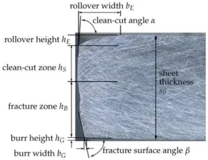
During stamping, a punch applies force to sheet metal against a die opening. The material initially deforms, then develops cracks that propagate through the thickness. When the material separates, the cut edge typically contains several characteristic zones:
Rollover: The rounded area near the entry side of the punch.
Burnished zone: The relatively smooth portion created by contact and shearing between the punch and die.
Fracture zone: The rougher area formed as cracks propagate through the material.
Burr:The protruding edge that can remain near the exit side of the cutting operation.
The relative size and appearance of these zones depend on material properties, sheet thickness, die clearance, cutting-edge condition, and other process variables.
Burr height alone does not describe every aspect of edge quality. Burr direction, sharpness, location, and consistency may also matter to the part’s function.
2. What Causes Burrs in Metal Stamping?
Excessive burr formation usually results from one or more interacting factors. The following are the main areas to investigate.
2.1 Incorrect Die Clearance
Die clearance is the gap between the punch and die cutting edges. It is one of the most important factors affecting the sheared edge.
When clearance is too large for the material and thickness, the material may undergo excessive deformation before separation, producing a larger rollover, a less favorable fracture pattern, or excessive burrs.
Clearance that is too small can increase cutting force, accelerate tool wear, and create other edge-quality problems. It should not be assumed that reducing clearance will always reduce burrs.
How to troubleshoot it:
- Confirm the specified sheet thickness and material grade.
- Verify the actual punch-to-die clearance and how it is defined.
- Compare the clearance with an appropriate recommendation for the material and operation.
- Inspect the cut edge and burr pattern before making adjustments.
- Conduct controlled trials when clearance changes are necessary.
There is no single clearance value that is correct for every metal stamping application. The appropriate value depends on material properties, thickness, part geometry, tooling design, and the required edge quality.
2.2 Worn Punches and Die Cutting Edges
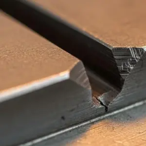
Cutting edges gradually deteriorate through repeated contact with the workpiece. Wear, chipping, rounding, and localized damage can change the way the material separates.
As a punch or die edge becomes worn, burr height may increase, cut quality may deteriorate, and dimensional variation may become more noticeable.
How to troubleshoot it:
- Inspect punch and die edges under suitable magnification.
- Compare burr height and edge appearance with earlier inspection results.
- Check whether the problem occurs across the entire cutting profile or only in specific areas.
- Review tool maintenance and sharpening records.
- Restore the cutting edge or replace damaged tooling components when necessary.
Sharpening should be performed according to the tooling design and maintenance requirements. After regrinding, verify the relevant die geometry and setup rather than assuming that the original cutting conditions remain unchanged.
2.3 Punch and Die Misalignment
Punch-to-die misalignment can create uneven clearance around the cutting profile. This may produce different edge conditions on opposite sides of a hole or along different sections of a blank.
Misalignment can also contribute to uneven loading, accelerated wear, and localized tooling damage.
How to troubleshoot it:
- Inspect die alignment and guiding components.
- Check the condition of guide posts, bushings, and other relevant locating features.
- Examine the distribution of burrs around holes and cut profiles.
- Look for uneven wear on the punch or die.
- Verify alignment after tooling maintenance or die reinstallation.
A burr that consistently appears on one side of a feature may be a useful diagnostic clue, but it is not conclusive proof of misalignment. The tooling should be inspected before corrective action is taken.
2.4 Incorrect or Inconsistent Material Thickness
Material thickness directly influences the shearing conditions and the clearance required for a stamping operation.
If the incoming material thickness differs from the specified value, the existing punch-to-die clearance may no longer be appropriate.
Material grade, hardness, temper, and mechanical properties can also affect deformation and fracture behavior.
How to troubleshoot it:
- Verify incoming material thickness at representative locations.
- Confirm the material grade and temper against the purchase specification.
- Compare burr measurements across material batches.
- Check whether the problem started after a material change.
- Review the process parameters before changing the die.
When material variation is suspected, measuring and verifying the material is preferable to making an unverified tooling adjustment.
2.5 Poor Tooling Condition or Inadequate Support
The condition of the complete die assembly matters, not just the punch and die cutting edges.
Loose or damaged components, inadequate guidance, incorrect stripper operation, poor workpiece support, or scrap accumulation can interfere with stable cutting and material movement.
These issues may contribute to inconsistent burr formation or other stamping defects.
How to troubleshoot it:
- Check the die assembly for loose, damaged, or incorrectly positioned components.
- Inspect stripper and material-guiding functions.
- Verify that scrap is being removed effectively.
- Check for abnormal movement or interference during the press stroke.
- Confirm that the tooling is assembled and maintained according to its design.
The corrective action should address the specific mechanical problem rather than treating every burr issue as a clearance problem.
2.6 Changes in Press Setup or Production Conditions
Changes in press setup, tooling installation, material feeding, or operating conditions may affect the consistency of the stamping process.
For example, a problem that begins immediately after a die changeover may indicate a setup or alignment issue. Burrs that gradually increase during a production run may point toward progressive tool wear or another developing process problem.
How to troubleshoot it:
- Establish when the burr problem first appeared.
- Compare initial samples with parts produced later in the run.
- Review recent tooling adjustments and maintenance.
- Verify material feeding and the stability of the production setup.
- Inspect the tooling before making multiple simultaneous adjustments.
A clear timeline helps narrow down the likely cause and avoids unnecessary changes to a previously stable process.
3. How to Identify the Root Cause of Stamping Burrs
When excessive burrs appear, changing the die clearance immediately is not always the best response.
A structured troubleshooting process helps distinguish tooling wear, clearance issues, misalignment, and material variation.
Step 1: Confirm the Burr Requirement
Check the engineering drawing, inspection specification, or customer-approved criteria.
Confirm whether the issue concerns burr height, sharp edges, burr direction, a specific feature, or an assembly requirement.
Without a defined acceptance criterion, it is difficult to determine whether the condition is nonconforming or whether corrective action is necessary.
Step 2: Locate and Measure the Burr
Identify the affected holes, outer profiles, or other cut edges.
Measure burr height using a suitable inspection method. Record the location and compare results across representative parts.
For critical components, use a method appropriate to the required measurement accuracy and inspection specification.
Step 3: Examine the Cut Edge
Inspect the rollover, burnished zone, fracture zone, and burr.
Compare the edge condition around the feature. Uneven burrs may indicate localized wear, clearance variation, or alignment issues, while a general increase across multiple features may suggest a broader tooling or material problem.
These patterns guide further inspection but should not replace direct verification.
Step 4: Check Tooling and Material
Inspect the cutting edges, punch-to-die clearance, die alignment, guiding components, and material thickness.
Review recent maintenance, material changes, and production setup records.
Step 5: Make a Controlled Correction
Address the verified cause first. Depending on the findings, this may involve sharpening a cutting edge, correcting alignment, restoring the specified clearance, replacing a damaged component, or resolving material variation.
Change one relevant variable at a time where practical, then verify the results through inspection.
Step 6: Confirm the Result
Inspect the corrected parts against the agreed requirements. Document the adjustment and verify that the improvement is sustained during production.
For recurring problems, retain burr measurements and corrective-action records to help prevent the issue from returning.
4. How to Prevent Excessive Burrs in Metal Stamping
Preventing excessive burrs requires control of the complete stamping process.
Maintain Appropriate Die Clearance
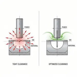
Establish clearance according to the material, thickness, cutting operation, tooling design, and required edge quality.
Document the relevant settings so that they can be checked during setup and maintenance.
Establish Tool Inspection and Maintenance Intervals
Inspect punches and die cutting edges at appropriate intervals based on tool condition, production history, and the consequences of burr formation.
Maintenance should be based on observed wear and process requirements rather than waiting until burrs exceed the permitted limit.
Control Incoming Material
Verify material grade, thickness, and relevant supply specifications. When changes in material condition are suspected, investigate them before making permanent tooling adjustments.
Standardize Setup and Changeover
Use documented procedures for die installation, alignment checks, feeding setup, and initial-part inspection.
Consistent setup helps reduce variation between production runs.
Monitor Critical Features During Production
For components with demanding edge-quality requirements, establish inspection frequency and measurement methods appropriate to the risk and production volume.
Monitoring trends can help identify a developing problem before a large quantity of parts is affected.
Evaluate Deburring When Necessary
Some components require a secondary deburring operation to meet edge-safety, assembly, or functional requirements.
Possible methods depend on the part geometry, material, burr location, and required finish. The selected method must not damage critical dimensions, functional surfaces, or thin features.
Deburring should not automatically replace root-cause correction when the stamping process is producing excessive burrs.
5. When Is Deburring Necessary?
Not every stamped part requires a separate deburring process.
The decision should be based on the engineering drawing, customer specifications, functional requirements, and actual edge condition.
Deburring may be necessary when:
- A sharp edge creates a handling or safety concern.
- A burr interferes with assembly or component fit.
- Electrical contacts or mating surfaces require controlled edge conditions.
- The specified burr limit cannot be consistently achieved through the stamping operation alone.
- Subsequent coating, finishing, or assembly requires a defined edge condition.
However, secondary deburring adds processing time and cost. It may also affect thin features, dimensions, or surface appearance if the method is not suitable.
For this reason, the preferred approach is to control burr formation during stamping and use secondary deburring when the part requirements justify it.
6. How Burr Control Affects OEM Component Quality and Cost
Burrs can have different consequences depending on the component’s function.
For electronic terminals and conductive contacts, edge condition may affect assembly, handling, or electrical-contact requirements. For brackets and formed components, burrs may interfere with mating parts or create handling concerns. For precision assemblies, an uncontrolled edge may affect fit or dimensional verification.
Excessive burrs can also increase inspection, sorting, rework, and secondary finishing costs.
For OEM buyers, it is useful to define critical edge requirements early in the project. Clear drawings and agreed inspection criteria help the manufacturer evaluate tooling, process controls, and any required secondary operations before production begins.
7. What Should OEM Buyers Specify to Control Burrs?
When requesting a quotation for custom stamped components, consider providing:
- The 2D engineering drawing and relevant 3D model.
- Material grade, temper, and thickness.
- Critical edges, holes, and functional mating features.
- Applicable burr-height or edge-condition requirements.
- Surface finish and appearance requirements.
- Production quantity and expected order volume.
- Inspection or validation requirements for critical features.
Not every part needs a numerical burr limit on every edge. Requirements should reflect the component’s function, assembly needs, and applicable customer specifications.
If burr limits are critical to performance, define them explicitly rather than relying on a general instruction such as “no burrs.”
Excessive burrs in metal stamping can result from incorrect die clearance,
worn cutting edges, punch-to-die misalignment, material variation, tooling problems, or unstable production conditions.
The most effective corrective action starts with measuring the burr, inspecting the cut edge, and identifying the actual cause. Appropriate tooling maintenance, material verification, controlled setup, and inspection help maintain consistent edge quality.
For OEM components, defining burr requirements early also helps align tooling design, production control, inspection, and cost expectations.