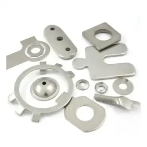
Sheet metal fabrication involves more than cutting and bending. Depending on the design and application, additional forming and secondary operations may be required to create mounting features, fastening points, locating features, clearance areas, reinforcement structures, and other functional details.
These features can often be produced using CNC turret punching, forming tools, dedicated dies, drilling and tapping equipment, or other secondary processes.
Selecting the appropriate forming method at the design stage can improve manufacturability, dimensional consistency, assembly efficiency, and overall production cost.
1. Countersunk Holes
A countersunk hole consists of a through-hole combined with a conical recess around the hole opening. The countersink allows the head of a flat-head screw or similar fastener to sit flush, or nearly flush, with the sheet metal surface.
Common Applications
Countersunk holes are commonly used to:
- Accommodate flat-head screws and allow a flush surface.
- Provide a clean, low-profile fastening solution.
- Reduce interference with adjacent components.
- Improve the appearance of finished assemblies.
Common Manufacturing Methods
Depending on material thickness, part geometry, production volume, and dimensional requirements, countersunk holes can be produced by:
- CNC turret punching with an appropriate forming tool.
- Drilling or machining operations using a countersink tool.
- A two-stage process involving a pilot hole followed by countersinking.
The countersink angle and depth should be specified according to the fastener requirements and applicable drawing tolerances.
2. Drawn or Extruded Holes
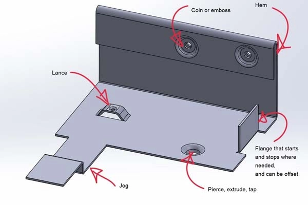
A drawn or extruded hole is formed by extending the sheet material around an opening to create a raised cylindrical section.
This feature is commonly used when additional material thickness is required around a hole, particularly for tapped holes or fastening applications.
Common Applications
Drawn holes can be used to:
- Provide additional material for internal threads.
- Increase thread engagement.
- Improve the strength of a tapped connection.
- Provide clearance or routing space for cables and fasteners.
Typical Manufacturing Process
A common process is:
- Punch or drill a pilot hole.
- Form the material around the opening using a dedicated forming tool.
- Tap the formed section when a threaded connection is required.
The final hole diameter, extrusion height, and wall thickness should be designed according to the required thread size and material properties.
3. Self-Clinching and Sheet Metal Riveting Features
Sheet metal assemblies may incorporate formed holes or clinching features that allow two components to be mechanically joined without conventional welding.
Depending on the design, these features can be produced using CNC forming tools, dedicated dies, or specialized riveting and clinching equipment.
Key Design Considerations
The forming height, wall thickness, hole diameter, and material thickness must be properly controlled to ensure sufficient mechanical strength.
For self-clinching or mechanically interlocked features, the dimensions should be determined according to the specific fastener and material manufacturer’s requirements rather than using a universal ratio.
This is particularly important for high-strength materials and thin-gauge sheet metal.
4. Tapped Extrusions
Tapped extrusions combine a formed hole with a threaded section.
The sheet metal is first formed to create additional material around the hole, after which the required internal thread is produced.
Typical Process
- Form the drawn or extruded hole.
- Verify the formed diameter and wall thickness.
- Tap the internal thread.
- Inspect the thread for dimensional accuracy and engagement.
The forming operation should always be completed before tapping. Attempting to tap an incorrectly formed or insufficiently thick section may result in stripped threads or inadequate thread engagement.
Depending on the material and application, tapping may be performed using conventional chip-forming taps or forming taps.
5. Embossed Bosses and Raised Features
Embossed bosses and raised features are formed by plastically deforming sheet metal using a dedicated forming tool.
They can be produced in a wide range of shapes depending on the functional requirements of the component.
Common Applications
Embossed features may be used to:
- Provide clearance for adjacent components.
- Maintain a specified assembly height.
- Create mounting or locating features.
- Improve component rigidity.
- Increase local structural strength.
Manufacturing Considerations
The achievable height of an embossed feature depends on the material type, material thickness, feature geometry, corner radius, and forming method.
Shallow embossments may often be formed in a single operation. Deeper features may require multiple forming stages, additional process features, or specially designed tooling to prevent excessive thinning, cracking, or distortion.
For complex geometries, the forming sequence should be evaluated during the DFM and tooling-development stages.
6. Slots and Locating Features
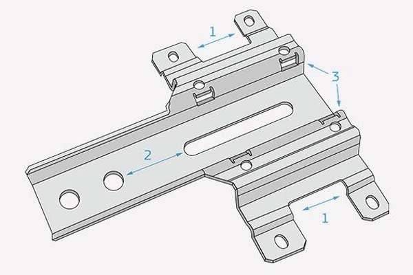
Slots can be designed in different geometries according to their intended function. Common examples include:
- Elongated or keyhole-style slots
- Bridge-shaped slots
- Formed locating slots
- Other application-specific positioning features
Common Applications
These features are typically used for:
- Positioning two mating components.
- Providing assembly alignment.
- Creating adjustable mounting positions.
- Facilitating installation and removal.
- Providing clearance for fasteners or components.
Manufacturing Methods
Depending on the geometry and production volume, slots may be produced by:
- Laser cutting
- CNC turret punching
- Forming dies
- Dedicated secondary tooling
For formed slots, the tooling design should account for material flow and the required dimensional tolerances.
7. Flanges
Flanges are formed edges or raised sections created by bending or forming sheet metal.
They can be used as both structural and functional features.
Common Applications
Flanges may be used to:
- Join two sheet metal components and create an enclosure structure.
- Improve the rigidity of panels and edges.
- Provide a fastening or locking interface.
- Create overlapping or interlocking sections.
- Protect cables and wiring from sharp sheet metal edges.
For enclosure applications, properly designed flanges can also contribute to dust protection, sealing, and overall structural rigidity.
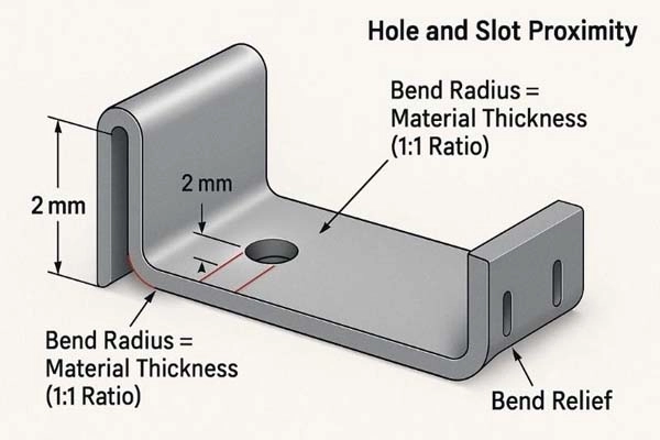
The flange height, bend radius, material thickness, and bend sequence should be considered during DFM to avoid tooling interference and deformation.
8. Reinforcing Ribs
Reinforcing ribs are formed features designed to increase the stiffness and structural stability of sheet metal components without significantly increasing material thickness.
Common configurations include:
- Linear ribs
- Cross ribs
- Triangular or gusset-style ribs
- Application-specific formed stiffeners
Common Applications
Reinforcing ribs can:
- Increase panel stiffness.
- Reduce deformation under load.
- Improve the stability of large flat surfaces.
- Reinforce bends and structural transitions.
- Reduce vibration and panel flexing.
Manufacturing Methods
Linear reinforcing ribs can typically be produced using dedicated forming tools or press-forming dies.
Gusset-style or triangular reinforcing features may require specialized tooling or forming operations, depending on their geometry and location.
Very small or closely spaced ribs may have tooling and material-flow limitations. Therefore, rib dimensions, spacing, depth, and orientation should be considered during the design stage.
Why These Features Matter in Sheet Metal Design
Functional forming features play an important role in the performance and manufacturability of modern sheet metal components.
For applications such as AI server infrastructure, energy storage enclosure sheet metal, liquid cooling equipment, telecommunications equipment, and industrial enclosures, these features may be required to achieve:
- Precise component positioning
- Reliable mechanical fastening
- Structural reinforcement
- Cable and component clearance
- Improved assembly efficiency
- Reduced part count
- Improved overall enclosure rigidity
The key is to select the appropriate feature and manufacturing process according to the material, thickness, geometry, tolerance requirements, production volume, and final application.
At Techsun, tooling development and process planning are considered together during the engineering stage to ensure that formed features are manufacturable, repeatable, and suitable for volume production.