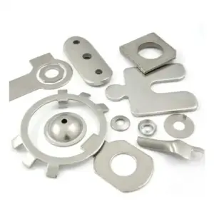
Design Considerations for Stamped Base Plates in Power Tools
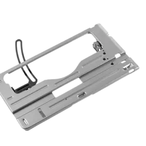
Metal base plates are important structural components in various power tools. Depending on the product design, they provide mounting surfaces, support adjacent components, and help maintain the required dimensional relationships within an assembled tool.
For power tool manufacturers, selecting the right manufacturing process for these components involves more than simply producing the required shape. Material selection, dimensional accuracy, flatness, hole positioning, forming characteristics, and assembly requirements all influence the final component quality.
Metal stamping is a suitable manufacturing option for many power tool base plates, particularly when repeatable dimensions and consistent production are required.
In this article, we explore the key design and manufacturing considerations for stamped base plates in power tools, from material selection and tooling design to dimensional inspection and production planning.
1. Understanding the Function of Power Tool Base Plates
Power tool base plates are metal structural components manufactured according to the design and assembly requirements of the equipment.
Depending on the application, a base plate may serve several functions:
- Providing a mounting surface for adjacent components
- Supporting mechanical assemblies
- Maintaining specified component positions
- Providing fastening locations through holes and formed features
- Contributing to the structural rigidity of the assembled product
Because these components interact with other parts, their dimensional characteristics can directly affect assembly fit and product functionality.
For OEM manufacturers, the base plate design should therefore consider both the individual component requirements and its relationship with the complete assembly.
2. Selecting the Right Material for Stamped Base Plates
Material selection is one of the first decisions in designing a stamped power tool base plate.
The appropriate material depends on the component’s structural requirements, thickness, geometry, forming conditions, surface requirements, and operating environment.
Common material options include:
Carbon Steel
Carbon steel is commonly considered for stamped structural components requiring suitable strength, rigidity, and cost-effective production.
Depending on the application, it may be used for:
- Power tool base plates
- Mounting plates
- Internal support components
- Structural brackets
The material grade and thickness should be selected according to the required mechanical properties and component design.
Stainless Steel
Stainless steel may be considered when corrosion resistance, durability, or specific surface characteristics are required.
However, its work-hardening behavior and forming characteristics should be considered during tooling and process development.
Aluminum
Aluminum may be suitable for power tool components where weight reduction is an important design consideration.
When using aluminum, engineers should evaluate alloy selection, temper, material thickness, forming limits, and potential surface damage during stamping.
Material Selection Considerations
Before confirming a material, OEM engineers should evaluate:
- Required mechanical properties
- Material thickness and dimensional variation
- Formability and bend characteristics
- Corrosion resistance requirements
- Surface appearance
- Material availability and production cost
The final material grade should always follow the customer’s engineering specifications and functional requirements.
3. Flatness and Dimensional Stability
Flatness is an important consideration for stamped power tool base plates, particularly when the component serves as a mounting or positioning surface.
Excessive deformation may affect assembly alignment, fastening conditions, and the fit of adjacent components.
Several factors can influence the flatness of a stamped base plate:
Material Thickness and Properties
Material thickness variation and mechanical properties can influence deformation during stamping.
The material specification should be reviewed before tooling development.
Part Geometry
Large flat areas, narrow connecting sections, asymmetrical profiles, and closely spaced openings may influence how a component behaves during stamping and forming.
Stamping Sequence
The order of blanking, piercing, and forming operations can influence dimensional stability.
For more complex components, the manufacturing sequence should be evaluated during tooling development.
Tooling Condition
Die clearance, punch and die alignment, tooling wear, and forming conditions can affect part consistency.
Flatness Inspection
Critical flatness requirements should be clearly identified on the engineering drawing.
Inspection methods and acceptance criteria should be agreed upon according to the component’s functional requirements.
For OEM projects, it is important to distinguish between overall flatness requirements and the flatness of specific mounting or contact surfaces.
4. Hole Positioning and Mounting Accuracy
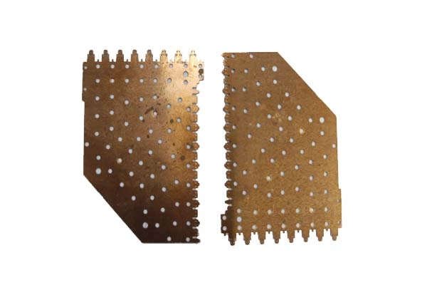
Power tool base plates may contain multiple mounting holes, slots, and openings for fastening and component positioning.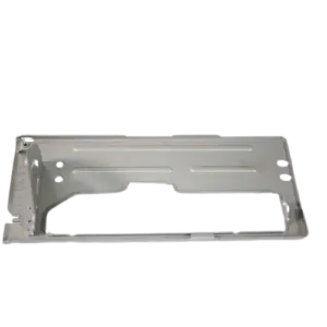
These features must be manufactured according to the specified dimensions and positional relationships.
Important design considerations include:
Hole-to-Hole Position
The distance between mounting holes should be defined using suitable drawing datums and dimensional tolerances.
Hole-to-Edge Distance
Sufficient material around holes helps maintain component integrity and reduce potential deformation during punching.
Slot Geometry
Slots and elongated openings should be evaluated according to their dimensions, orientation, and assembly function.
Hole-to-Bend Relationship
When a base plate includes formed edges or bent features, the distance between holes and bend lines should be considered.
Bending can influence nearby features, so their positions should be reviewed during process planning.
Assembly Compatibility
Mounting holes should be evaluated together with the corresponding screws, fasteners, and adjacent components.
For this reason, OEM drawings should identify critical mounting dimensions and functional interfaces rather than relying only on general dimensional tolerances.
5. Bend Geometry and Forming Requirements
Some power tool base plates include formed edges, flanges, or other features that provide additional rigidity or support assembly.
These features introduce additional manufacturing considerations.
Inside Bend Radius
The appropriate bend radius depends on material grade, thickness, temper, and forming conditions.
An unsuitable bend radius may increase the risk of cracking or surface damage.
Bend Angle Accuracy
Bend angles should be specified according to the component’s assembly and functional requirements.
Material springback should be considered during process development.
Flange Dimensions
Flange length and geometry must provide sufficient space for the intended assembly and forming operation.
Forming Sequence
For components with multiple bends or formed features, the sequence should be evaluated to avoid tooling interference and dimensional variation.
Early review of these details can help reduce unnecessary tooling adjustments and production difficulties.
6. Choosing the Right Stamping Tooling Strategy
The tooling strategy for a power tool base plate depends on its geometry, number of operations, dimensional requirements, and expected production volume.
Two common approaches are single-operation stamping and progressive die stamping.
Single-Operation Stamping
Single-operation stamping may be appropriate for components with relatively simple geometries or projects where a more straightforward tooling arrangement is suitable.
Different operations can be performed using separate dies or production steps.
The suitability of this approach depends on the part design, production quantity, and required manufacturing efficiency.
Progressive Die Stamping
Progressive die stamping integrates multiple operations into a continuous production sequence.
Depending on the component design, operations may include:
- Blanking
- Piercing
- Notching
- Bending
- Forming
Progressive tooling can be suitable for repeat production of components with multiple features and consistent production requirements.
How Should OEM Buyers Choose?
The decision should consider:
- Component geometry and complexity
- Number of stamping operations
- Material type and thickness
- Required dimensional consistency
- Estimated production volume
- Initial tooling investment
- Expected long-term production demand
A suitable tooling strategy should balance manufacturing feasibility, tooling cost, production efficiency, and finished-part quality.
7. Burr Control and Edge Quality
Burrs are a common consideration in stamped metal components.
For power tool base plates, burr conditions may affect handling, assembly, adjacent components, and the quality of finished edges.
Burr formation can be influenced by:
- Punch and die clearance
- Tooling wear
- Material properties
- Material thickness
- Punching conditions
During engineering review, the required burr height, direction, and acceptable edge condition should be identified.
Where necessary, additional deburring or edge-finishing operations can be evaluated according to the component design.
It is important to specify realistic burr requirements based on the actual function of the component rather than applying unnecessarily strict requirements to every edge.
8. Surface Finish and Corrosion Protection
Surface requirements should be considered early in the design process.
Depending on the power tool application, a base plate may require a specified surface condition or additional finishing treatment.
Relevant considerations include:
- Surface scratches and visible defects
- Corrosion resistance
- Coating or plating specifications
- Masking requirements
- Dimensional changes associated with finishing
- Contact surfaces that must remain protected
The selected finishing method should be compatible with the base material and the component’s intended application.
OEM customers should clearly specify appearance requirements and applicable finishing standards in the engineering documentation.
9. Quality Inspection for Stamped Power Tool Base Plates
Inspection requirements should be established according to the component drawing and its functional characteristics.
For stamped base plates, important inspection items may include:
Dimensional Inspection
Check overall dimensions, hole positions, slot dimensions, and critical formed features.
Flatness Inspection
Verify specified mounting or reference surfaces according to agreed inspection methods.
Burr and Edge Inspection
Evaluate burr conditions and edge quality against customer acceptance criteria.
Forming Inspection
Check bend angles, flange dimensions, and other formed characteristics where applicable.
Material Verification
Verify material grade, thickness, and available material documentation.
Surface Inspection
Check for scratches, dents, tool marks, and other appearance-related conditions according to agreed requirements.
Initial samples can be submitted for customer evaluation and approval before repeat production.
A clear inspection plan helps ensure that important component characteristics are evaluated consistently.
10. What OEM Buyers Should Provide When Requesting a Quote
When sourcing custom stamped power tool base plates, complete technical information helps manufacturers evaluate the project more accurately.
OEM buyers should prepare:
- 2D engineering drawings
- 3D CAD files, if available
- Material grade and thickness
- Critical dimensions and tolerances
- Flatness and hole-position requirements
- Burr and edge-quality specifications
- Surface finishing requirements
- Estimated annual production volume
- Initial sample quantity
- Packaging and inspection requirements
It is also helpful to identify the component’s assembly function and any critical interfaces with adjacent parts.
With these details, a metal stamping manufacturer can evaluate manufacturing feasibility, tooling requirements, suitable production processes, and inspection methods.
Designing a reliable stamped base plate for a power tool requires coordination between material selection, part geometry, tooling strategy, dimensional control, and assembly requirements.
For OEM manufacturers, addressing these factors during the engineering stage can help reduce production difficulties, improve component consistency, and support a smoother transition from sampling to repeat production.
Techsun provides custom metal stamping solutions for power tool components, including stamped base plates, belt clips, battery terminals, motor mounting brackets, and other metal parts.
With in-house tooling development and stamping presses ranging from 25 to 300 tons, Techsun supports projects from engineering drawing review and sample development to repeat production.